


Hydraulic Assisted Bridges
Contents |
[edit] Introduction
Hydraulically Assisted Bridges (HAB) is a new concept in bridge design which incorporates an integrated hydraulic system into the bridge in order to carry more weight. The system is most suitable for arch-based bridges in which the main forces are directed in a horizontal sideways direction.
The hydraulic system is integrated into the main load bearing members of the bridge can be minimally controlled by computers; however, if calibrated and constructed accurately, the system has the possibility for non-electronic autonomic self-adjustment which entails low maintenance cost and a reduced safety risk in an event of an electrical malfunction.
[edit] How it works
The bridge is chiefly appropriate for bridges which inherently distributes their forces in a lateral/horizontal direction at the supports at the reactions. This includes bridges based on the arch, such as bowstring arch bridges. At the midpoint of the arch there is a pinned connection, essentially making it a three hinged arch (two at the supports). This implies any loading will cause the arch to spread out and this is taken advantage by the hydraulic system.

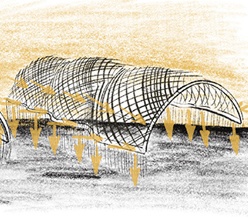
[Fig.1: How the Hydraulically Assisted Bridge Works]
[edit] Supports
As the load causes the three hinged arch to spread out, the end of the members house a hydraulic piston. This piston is held in place via a pined connection so it can slide into the shaft easily. As the hydraulic fluid is pushed under pressure, the fluid travels through pipes eventually leading to a vertical shaft leading to the mid-span of the bridge.
Figure 2 shows details on the roller pin support and the O-rings of the piston.

[Fig.2: Zoomed in Image of How the Pins and Pistons Connect]
[edit] Mid-span of bridge
At the mid-span, the high pressure hydraulic fluid causes another piston to become raised. And this causes it to push with a vertical force, hence counteracting the load that was initially implied. This is where calibration and calculation is required.
The pressure provided by the hydraulic fluid related to the formula: P=F/A or pressure = force per unit area. Hence the system can be calibrated to provide a certain amount of vertical force provided by the vertical hydraulic by changing the diameter of the piston and shafts. The correlation is, the smaller the diameter of the piston/shaft assembly, the higher the pressure. The piston and shaft assembly of the vertical column can also be altered and need not be equivalent to the pistons at the supports.
Importantly, you can cause the vertical piston to displace too much than required or displace by too little, hence detailed calculation is required.
[edit] Advantages
If accurately calibrated, there is no need for computers to control the hydraulic actuators. The hydraulic rams can be in motion only by the loading applied to it. That is to say, if a certain load is applied on the bridge, the hydraulic ram applies an appropriate force upwards to counteract any deflections. This implies that there is very little maintenance concerning automated systems and in situations such as blackouts or malfunctions, the bridge will not be in any immediate concern for failure.
As a result of applying a force upwards that is dependent on the load and displacement of the bridge, the quantity of material required to construct the bridge is reduced. The material alone does not have to handle all imposed loading; the load is distributed onto the hydraulic rams. Consequently, less money can be used in purchasing materials and the project cost is reduced (arguably, the money may be spent on the hydraulic systems).
Certainly, elegant bridges may be constructed with thinner structural members, which can increase its aesthetic and social impact on the community around it. What is more is that if the load becomes to great and causes the mid-span piston to go down, then the support pistons will push inwards resulting in the arch heading upwards; hence they maintain equilibrium.
 [Fig.3: How Reversal of Hydraulic Fluid Still Results in Equilibrium]
[edit] Disadvantages
As a consequence of the vertical hydraulic column being required to be located in the centre of the arch, there are intrinsic complications. For example, to install the hydraulic pipe connections would require tunnelling either underground or to lay the pipes over ground; this entails placing construction workers in hostile environments and they have to be specialised workers. This requires extensive training which can affect the building project economically.
Vertical column type hydraulic bridges may never be used in arch bridges required to span gaps which are very high in the context of the altitude of the locale. Without solid ground for the column to rest on, the action of the hydraulic will cause deflection and eventual failure. However, there are methods to overcome this problem.
Possible hydraulic failure at the three main points can be caused by very high forces and pressures due to excessive loading on the main bridge. The high pressure of hydraulic fluid can cause failure at any O-ring and gasket seals rendering it useless.
[edit] Overcoming the disadvantages
The disadvantages of having to lay hydraulic pipes underground in hostile conditions and also having no possible use in arches in high altitude applications can be resolved by eliminating the single vertical hydraulic column. Rather it can be replaced by utilising hydraulic components placed at an angle, thus connecting the supports to mid-span. However, this would require calibration of the diameter of the hydraulic face in order to provide additional forces with a higher vertical component. Otherwise, angling the hydraulic components nearer to vertical will provide a greater vertical force.
As a result, with this method, the hydraulic assisted bridges can be built over hostile gaps and at higher altitudes which is very beneficial.
The problems with seal failure can be resolved by adding several, thicker O-rings and gaskets and increasing the area of the hydraulic face, reducing pressure which reduces the possibility leaks and failures.

[Fig.4: How arranging the pistons at an angle eliminates the need for pipes underground at mid-span]
[edit] Potential applications
As stated before, this innovation is appropriate for, but not wholly restricted to, arch bridges. Hence it could be applied to almost all current applications of arch bridges which include:
- Pedestrian footbridges.
- Water transportation.
- Vehicular transportation.
- Light vehicles.
- Freight vehicles.
- Railway transportation
Indeed the hydraulic system can be applied in novel shaped bridges. Figure 5 shows why it would work on a 'Y'-shaped bridge because the protruding members are displaced by the same angle. However, they move different lengths at different spots hence the hydraulic piston at 'x' (the closer to the centre-line) will be depressed first causing the piston at 'y' to move upwards, assisting in holding the load.

[Fig.5: 'Y' Shaped bridge utilising the hydraulically assisted system]

[Fig.6: The Hydraulic System applied to other shaped bridges]
[edit] Related articles on Designing Buildings Wiki
Featured articles and news
ECA Blueprint for Electrification

Delivering the UK’s Transition to Clean Power; with recommendations for the mosaic of interconnected challenges.
Grenfell Tower Principal Contractor Award notice

Tower repair and maintenance contractor announced as demolition contractor.
Passivhaus social homes benefit from heat pump service
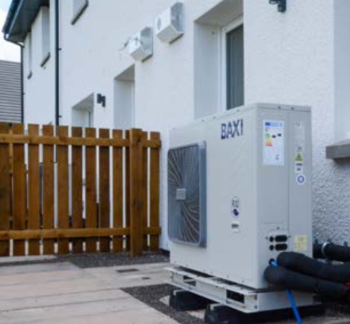
Sixteen new homes designed and built to achieve Passivhaus constructed in Dumfries & Galloway.
CABE Publishes Results of 2025 Building Control Survey

Concern over lack of understanding of how roles have changed since the introduction of the BSA 2022.
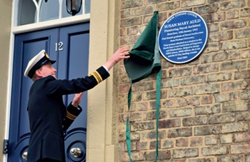
British Architectural Sculpture 1851-1951

A rich heritage of decorative and figurative sculpture. Book review.
A programme to tackle the lack of diversity.
Independent Building Control review panel
![]()
Five members of the newly established, Grenfell Tower Inquiry recommended, panel appointed.
Welsh Recharging Electrical Skills Charter progresses
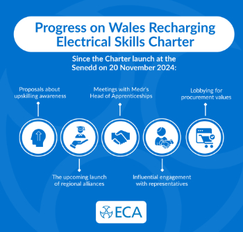
ECA progressing on the ‘asks’ of the Recharging Electrical Skills Charter at the Senedd in Wales.
A brief history from 1890s to 2020s.
CIOB and CORBON combine forces

To elevate professional standards in Nigeria’s construction industry.
Amendment to the GB Energy Bill welcomed by ECA

Move prevents nationally-owned energy company from investing in solar panels produced by modern slavery.

Gregor Harvie argues that AI is state-sanctioned theft of IP.

Heat pumps, vehicle chargers and heating appliances must be sold with smart functionality.
Experimental AI housing target help for councils

Experimental AI could help councils meet housing targets by digitising records.
New-style degrees set for reformed ARB accreditation
Following the ARB Tomorrow's Architects competency outcomes for Architects.
BSRIA Occupant Wellbeing survey BOW
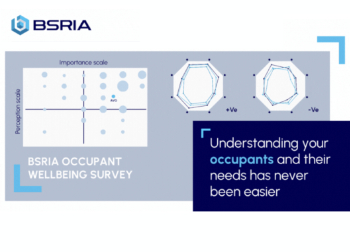
Occupant satisfaction and wellbeing tool inc. physical environment, indoor facilities, functionality and accessibility.

Preserving, waterproofing and decorating buildings.